Visual Line Following
The following tutorial is one way to use a vision system to identify and follow a line.
The system uses:
- single CCD camera
- USB Digitizer
- Zigbee module
- Pentium CPU on board
- Left, Right differential motors

Example Images
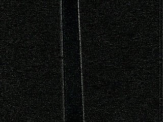
To get a better idea of what we're trying to accomplish lets first look at some sample pictures that the BucketBot took. The images are from the CCD camera mounted to the front of the BucketBot angled towards the ground.
Note that we have not done any calibration of lighting adjustments. The images are straight from the camera.
If it worth mentioning that the lines are created by black electrical tape stuck on moveable floor tiles. This allows us to move the tiles around and experiment with shapes quite easily.


Lighting Issues...
Bad lighting can really cause problems with most image analysis techniques (esp. when thresholding). Imagine if a robot were to suddenly move under a shadow and lose all control! The best vision techniques try to be more robust to lighting changes.
To understand some of those issues lets look at two histograms from a straight line image from the previous slide. Next to each of these images are the images histogram. The histogram of an image is a graphical representation of the count of different pixel intensities in the image.
Edge Detection
In order to follow the line we need to extract properties from the image that we can use to steer the robot in the right direction. The next step is to identify or highlight the line with respect to the rest of the image. We can do this by detecting the transition from background tile to the line and then from the line to the background tile. This detection routine is known as edge detection.
The way we perform edge detection is to run the image through a convolution filter that is 'focused' on detecting line edges. A convolution filter is a matrix of numbers that specify values that are to be multiplied, added and then divided from the image pixels to create the resulting pixel value.
Edge Detection
Here are two sample images with the convolution edge detection matrix run after normalization:


It is interesting to note that while the convolution filter does identify the line it also picks up on a lot of speckles that are not really desired as it causes noise in the resulting image.
Also note that the detected lines are quite faint and sometimes even broken. This is largely due to the small (3x3) neighborhood that the convolution filter looks at. It is easy to see a very large difference between the line and the tile from a global point of view (as how you and I look at the images) but from the image pixel point of view it is not as easy. To get a better result we need to perform some modifications to our current operations.
Modified Line Detection
To better highlight the line we are going to:
1. Use a larger filter; instead of a 3x3 neighborhood we will use a 5x5. This will result in larger values for edges that are "thicker". We will use the following matrix:
| -1 | -1 | -1 | -1 | -1 |
| -1 | 0 | 0 | 0 | -1 |
| -1 | 0 | 16 | 0 | -1 |
| -1 | 0 | 0 | 0 | -1 |
| -1 | -1 | -1 | -1 | -1 |
2. Further reduce the speckling issue we will square the resulting pixel value. This causes larger values to become larger but smaller values to remain small. The result is then normalized to fit into the 0-255 pixel value range.
3. Threshold the final image by removing any pixels lower than a 40 intensity value.
The results of this modified technique:


We now nicely see the line edges and most of the noise speckles are gone. We can now continue to the next step which is how to understand these images in order to map the results to left and right motor pulses.
Center of Gravity
There are many ways we could translate the resulting image intensities into right and left motor movements. A simple way would be to add up all the pixel values of the left side of the image and compare the result to the right side. Based on which is more the robot would move towards that side.
At this point, however, we will use the COG or Center of Gravity of the image to help guide our robot.
The COG of an object is the location where one could balance the object using just one finger. In image terms it is where one would balance all the white pixels at a single spot. The COG is quick and easy to calculate and will change based on the object's shape or position in an image.
To calculate the COG of an image add all the x,y locations of non-black pixels and divide by the number of pixels counted. The resulting two numbers (one for x and the other for y) is the COG location.
Let's do that for a couple images and see what we get!
Center of Gravity
The COG location is the red square with a green line from the center of the image to the COG location.


Based on the location of the COG we can now apply the following conditions to the robot motors:
- When the COG is to the right of the center of screen, turn on the left motor for a bit.
- When the COG is on the left, turn on the right motor.
- When the COG is below center, apply reverse power to opposite motor to pivot the robot.
You can also try other conditions such as when the distance of the COG to the center of screen is large really turn up the motor values to try to catch up to the line.
Let's have a look at some more results ...

PROJECT CODE:
' initialize starting servo values
pan = GetVariable("PAN_SERVO")
tilt = GetVariable("TILT_SERVO")
steering = GetVariable("STR_SERVO")
throttle = GetVariable("THR_SERVO")
' get the size (width or height) of the current bounding box
size = GetVariable("COG_BOX_SIZE")
' if it is equal to "" then no object was detected
if size <> "" then
' get the horizontal center of gravity
cogX = GetVariable("COG_X")
' pan left
if cogX < 140 then
pan = pan - 2
end if
' pan right
if cogX > 180 then
pan = pan + 2
end if
' get the vertical center of gravity
cogY = GetVariable("COG_Y")
' tilt down
if cogY < 100 then
tilt = tilt - 2
' tilt up
end if
if cogY > 140 then
tilt = tilt + 2
end if
'steer where it looks
'adjust 300 accordingly, 300 is due to the steering servo being offset
steering = 300 - pan
'get the distance variable to control the movement
cogSize = GetVariable("COG_BOX_SIZE")
' forward
if cogSize < 30 then
throttle = 130
' reverse
elseif cogSize > 45 then
throttle = 160
else
throttle = 150
end if
SetVariable "STR_SERVO", steering
SetVariable "THR_SERVO", throttle
SetVariable "PAN_SERVO", pan
SetVariable "TILT_SERVO", tilt
end if

No comments:
Post a Comment